Audio and Electroacoustic System Engineering
Audio Engineering
Loudness
Frequency and bandwidth
f0
F0 is the frequency corresponding to the point where the vibration plate vibrates most strongly when the speaker starts to vibrate from the low range, and the frequency corresponding to the first time the impedance value reaches its maximum value on the impedance curve (i.e. Zmax) is called the resonant frequency or resonance frequency of the speaker unit, abbreviated as F0. The input is a swept frequency signal of equal amplitude, and the voltage across the speaker is viewed in real time with a voltmeter. The voltage corresponds to f0 at the maximum.
https://wiki.aalto.fi/pages/viewpage.action?pageId=149890776
fh
f0 is mainly caused by the rear cavity, fh is the problem of the front cavity. The change in high frequency is the extrusion of the front cavity.
Q Value
Q value: represents the resonance quality factor at the resonance point f0.
The higher Q means that the curve is sharper, and in terms of vibration phenomenon, it is not easy to stop the vibration, so the bass will sound muddy. But in the case of small speakers, because the bass is not easy to do well, so the Q value is higher.
Sensitivity
Sensitivity is a microphone that indicates its true output loudness, the lower it is the higher the gain that needs to be added to the pre-amp.
$$
EG1 = \frac{-54.5 dBV}{Pa (1.85 mV)}, 1 Pa = 94 dB SPL (1000 Hz)
$$
$$
EG2 = \frac{-29 dB re 1V}{Pa (35mV @ 94 dB SPL)}, ±2dB @ 1Khz
$$
Eg1 needs 25.5 dB of gain to be the same volume level as EG2 output. The louder it is the louder it is.

This microphone is sensitive: -37dBFS, which is 94dB SPL @1kHZ is in accordance with the 1Vrms to control, so now the sensitivity can be understood as -37dBV. because the full scale here is 1Vrms.
Some Important formulas
$$
Frequency = rate * channels * sample \ bits
$$
$$
1 Pa @ dB SPL = \
10 log_{10}(12 / PB2) = \
20 log_{10}(1 / PB) = \
-20 log_{10}(PB) =\
-20 log_{10}(2(10-5)) =\
-20 (log_{10} 2 + log10 10-5) =\
-20 ((log_{10} 2) – 5) =\
100 – 20 log_{10} 2 ≈ 93.9794 dB SPL\
$$
$$
0 dB SPL = 10 log10(0.000022 / 0.000022) = 10 log10(1) = 10 (0) = 0.
$$
$$
dBPa = 20*log(x \ Pa)
$$
$$
dB = 20 log_{10} (V_{input} / V_{output \ or \ reference \ voltage})
$$
$$
dB = 10 log_{10} (P_{input}/P_{output \ or \ reference \ power})
$$
The formula for Volts to dBV conversion is:
$$
dBV = 20*log(xV)
$$
6dB => 2 times voltage, 3dB => 2 times power.
And hence, the reverse formula for dBv to Volts conversion is:
$$
Volts = 10^{\frac{dBV}{20}}
$$
Power level in decibels relative to 1 V (volts) power. dB in Acqua acoustic test is 1 Vrms (root mean square value of voltage) as the reference voltage value. So at this point, 0 dB is 1 Vrms, the maximum value. Power level relative to 1 mW (milliwatt) power, in decibels.dBm = decibel of milliwatt (mW)
$$
dBm = 10 *log(xm \ W) \
10 log_{10}(signal \ power/1 mW) \
1 mW = 0 \ dBm \
10 mW = 10 \ dBm \
100 mW = 20 \ dBm \
40 W = 46 \ dBm
$$
$$
20 log_{10}(2)dB = 6.02 dB \
20 log_{10}(3)dB = 9.54 dB \
20 log_{10}(4)dB = 12.04 dB \
20 log_{10}(5)dB = 13.97 dB \
20 log_{10}(6)dB = 15.56 dB \
$$
**dBFS = dBm0 = dBm relative to a 0 transmission point = dB relative to digital overload point, 0dB0v = full scale.. **
dBv is a logarithmic voltage ratio with a voltage reference of 1 Volt.
1 V is equivalent to 0 dBv.
Electroacoustic System Hardwares
Loudspeaker
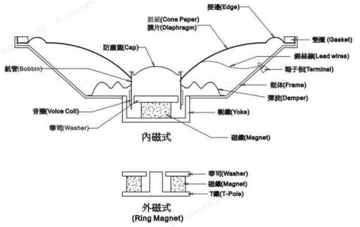
The three main parts of the speaker.
Diaphragm: 振膜
Voice coil:音圈
Magnetic circuit: 磁路
Diaphragm motion produces an analogous electrical signal.
The diaphragm movement generates an analog signal, while the thick diaphragm affects frequency response, transient response and sensitivity.
Large diaphragm size: high sensitivity, narrow band width.
Small diaphragm size: low sensitivity, wide bandwidth.
Active: It has an internal oscillation source, which can start oscillating as long as it is connected to DC power.
Passive: that is, its internal without a source of vibration, to be connected to AC to start the vibration, coils and magnets, the current goes up as soon as it passes, down as soon as it is disconnected, so that you can produce a vibration circuit, so that by controlling this one up and down, I can control the frequency of this vibration. Once the electricity is energized, there is a magnetic, up, a disconnect, no magnetic down. Passive include: oscillator, electromagnetic coil, magnet, vibration diaphragm and shell composition. We only give high and low high and low, this passive will ring.
Microphone
Microphone type
- Dynamic Mic: Dynamic Coil
- Condensor: Condenser Microphone
- Pure Condensor: Pure condenser microphone
- Electret condenser (“pre-polarized”) condenser microphones
- MEMS (micro-electro-mechanical system) microelectromechanical microphones
- Miniature electret condenser: Miniature electret condenser microphone
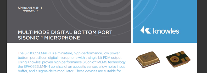
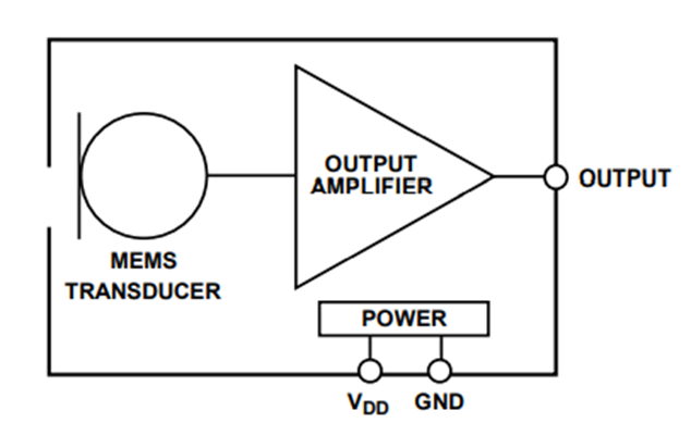
MEMS microphones.
We generally choose MEMS microphones. A MEMS microphone is composed of a MEMS chip and an ASIC chip.
MEMS microphone classification and selection: https://www.klippel.de/s
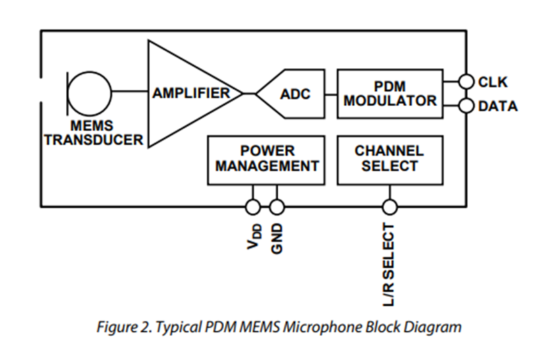
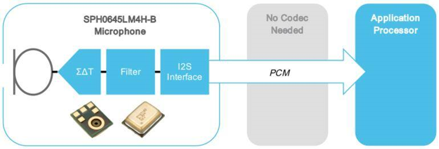
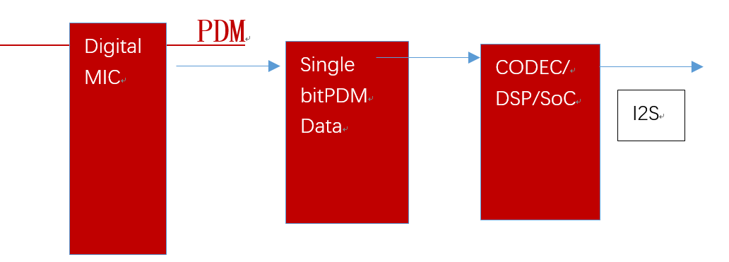
The voltage value of the output analog signal of a digital microphone is usually PDM or I²S. The output signal of a digital signal microphone can communicate directly with a DSP or SoC, which does not need a Codec at this time, thus reducing the cost of the system.
The microphone is based on the clk to adjust the value of the size, the digital microphone can be adjusted by adjusting the sensitivity to achieve the effect of AOP constant. Sensitivity and AOP are related, sensitivity can be reduced to improve AOP.
The AOP effect will be higher with differential signals. For the microphone to distort 1% of the time the point, and AOP is generally 5, 6 dB difference.
Digital (PDM) Microphones
https://www.cuidevices.com/blog/analog-or-digital-how-to-choose-the-right-mems-microphone-interface
A PDM microphone is a digital microphone. Digital microphones generally take 4 to more pins, but analog ones generally three. The advantage of analog microphones is that they are small in size and do not take up much space generally *2.5mm,*3.35mm0.88mm or smaller. But PDM microphone is generally 3mm, *4mm,*1mm, if we consider the alignment and space size, too small, we will have to consider the analog microphone.
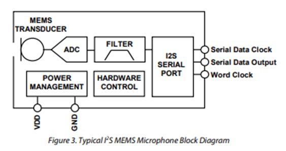
I2S microphone
The I2S microphone output can then be output directly to the I2S device without a codec.
https://www.digikey.com/en/product-highlight/k/knowles/i2s-output-digital-microphone
https://www.digikey.com/en/product-highlight/k/knowles/i2s-output-digital-microphone
I2S microphone example: ADMP441 , I2S can easily be replaced, but the mainstream is still PDM now.
Audio Power Amp (PA)
The amplification can be the gain factor.
There is no electrical signal from the horn, because the horn is a passive device, so the measured signal is actually the PA.
Here are the basic params to describe the Audio PA. We will only use the sin waves to do the testing here.
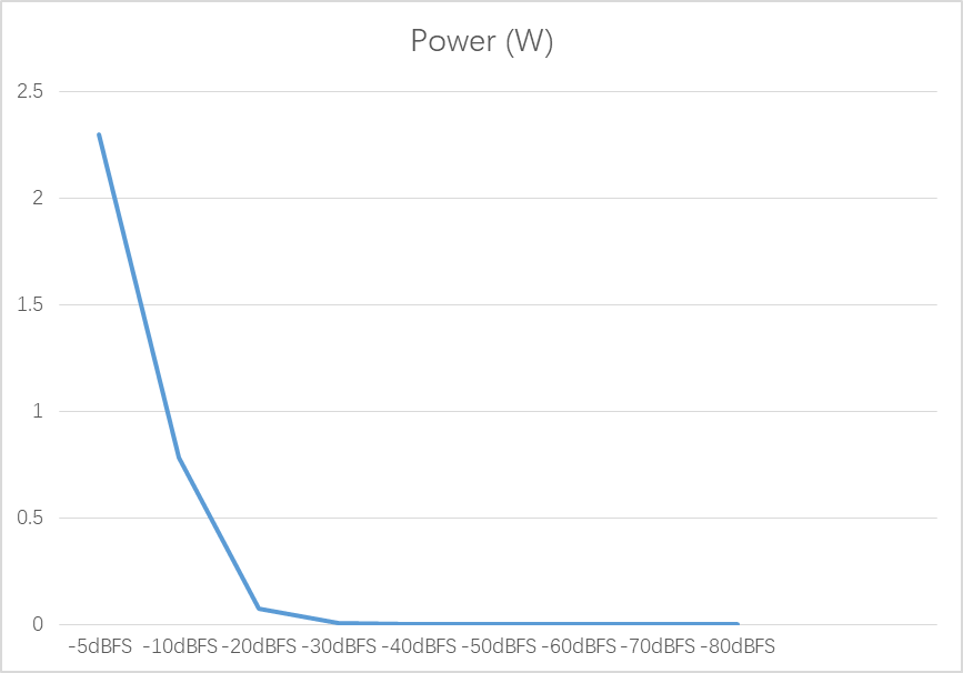
Since every 10 dBFS decrease, then the theoretical value of the measured power will decrease by a factor of 10.
10dBFS = 10log(P1/P2)
1dBFS = log(P1/P2)
(P1/P2) = 10
Therefore it can be seen that P1 should be ten times larger than P2, which is the parameter after the change.
Channel: 我们对于耳机一般选择双声道(dual),对于喇叭而言,我们既可以双声道也可以单声道。
20hz ~ 20kHz ± 0.2 dB :代表以1000Hz为参照的测量.
Loudness Level(电声压)
RMS level (Rooted Mean Square level): Mean Square* level
MOL (Maximum Output Level): Maximum output level / minimum output level
Relative Level (电位差)
Dynamic Range
*动态范围Dynamic Range_1kHz-60dB*
Dynamic range refers to the system playback, the maximum undistorted output power and static system noise output power ratio of the logarithmic value
Dynamic range is the difference between two signals, usually we just listen to a large signal (0 dB), and then listen to a small signal (-60 dB) or need to subtract this result with 60 to see the difference.
Sweep in the AP software, we have to choose: 20 Hz - 20 kHz, 1/6 Oct (61 pt, slow), and do not choose Append Graph Data, this option will keep the last results.
Distortion
*总谐波失真和左右声道相位差_MaximumOutputLevel &THD+N& InterchannelPhase_1kHz_0dB互调失真_IMD_70+7K*
· THD+N : 总协调参数失真+噪音
Distortion of the sound after amplification. The smaller it is, the better.
IMD: Intermodulation distortion (20 Hz-20 kHz, 1/6 Oct, 61: points)
MTD (Multi-tone distortion)
The type of non-linearity, when the amplitude of the output levels are both compressed and distorted is called saturation.
Frequency Response
频率响应_Freq_sweep_61_0dB*
Generally, the flatter the better.
Flatness: flatness
Noise
*底噪_mute_silence_0dB*
*信噪比Dynamic Range_1kHz-60dB*
The noise will be noticeable and will clearly distort the outpu
· Signal-to-Noise Ratio :底噪率
· POP noise
· SNR (Signal-noise ratio):Signal-to-noise ratio = received signal power/noise power
Power Spectral Density: No = 10^(-14.4) W/Hz * B (Bandwidth: 20~20000Hz)。Noise Power/Variance。 NoB单位dBm。来源:
SNR
Dial 0dB first and then click noise. First measure the maximum electric sound pressure and then measure the bottom noise is also OK, count the difference. Signal-to-noise ratio and dynamic range is about the same. If you really can not switch, you can: maximum volume - noise bottom noise.
Crosstalk
*Crosstalk_left_only_1kHz_0dB*
*Crosstalk_right_only_1kHz_0dB*
*Crosstalk_sweep L to R 20to20k*
The crosstalk curves from L to R are tested separately.
*Crosstalk_sweep R to L 20to20k*
The crosstalk curves from L to R are tested separately.
It means that there is no correlation between the two channels and they are independent of each other.
Phase
左右声道相位差_MaximumOutputLevel &THD+N& InterchannelPhase_1kHz_0dB*
We generally use 16bit audio for testing.
The difference between speakers and headphones is Balanced and Unbalanced, other operations are the same.
Boost and Charge pump
Boost is high because of the DCDC, which uses an inductor. (The use of inductor current can not change the characteristics of the sudden)
Charge pump is reversed by capacitor, because the capacitor is very stable at both ends, but charge pump is generally very small boost multiplier, with the use of capacitors. charge pump is a charge pump boost, with the capacitor charging characteristics to complete the boost. charge pump uses capacitive energy storage, the same as the pump (a tube a tube), the charge through the capacitor (a capacitor Capacity size of the power) in series to boost the way. Charge after use, use after recharge.
boost
advantages: Any voltage value efficiency can be to more than 90%, do a good company, can do 95%
Disadvantages: need inductors, occupy a lot of area, but also need to prevent EMI mess.
charge pump
advantages: Using the capacitive method, the volume advantage comes out.
Disadvantages: VOUT voltage for the vin voltage of the integer times when the efficiency reaches the highest, other times, the efficiency will have an impact.
Modulation

Audio Files Formats
Pulse Code Mudulation
PCM is multi-segmented to save the audio data files of CDs and PCM files are very easy to edit.
| Pulse modulation | |
|---|---|
| Analog | PAM · PDM · PPM |
| Digital | PCM · PWM |
](/../images/image-20220830185640372.png)
8, 9, 11, 12, 13, 14, 15, 15, 15, 14…etc. They are binary encoded to obtain a set of numbers: 1000, 1001, 1011, 1100, 1101, 1110, 1111, 1111, 1111, 1111, 1111, 1111…etc. These digital data can then be processed by DSPs or general CPUs for specific applications.
A unit of audio data is represented by multiple bytes, and a unit is represented by a fixed amount of bytes in a segment. So its effect is determined by the sample rate and depth.
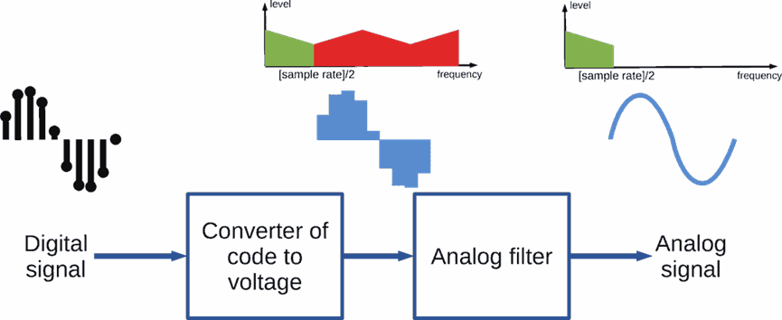
The filter filters the input square wave into a sinusoidal signal. the AP’s filter is to filter the square wave signal into a sinusoidal signal, which incidentally also reduces noise.
PWM Modulator
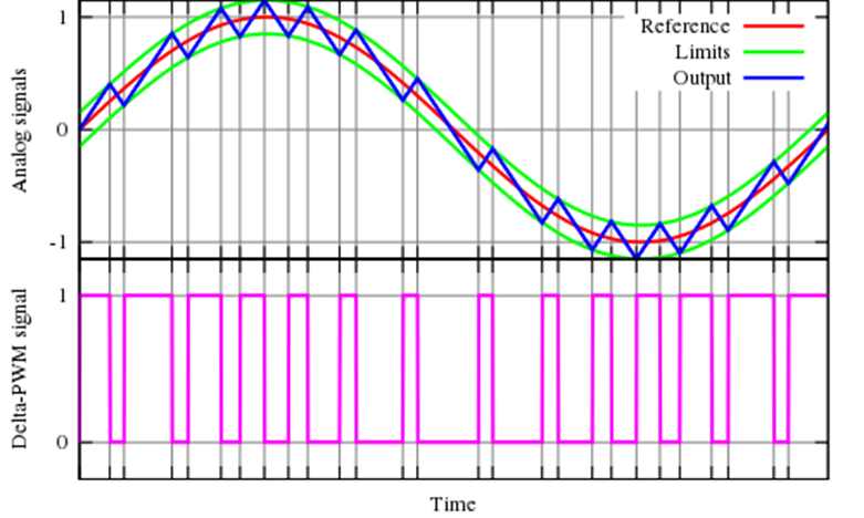
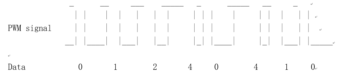
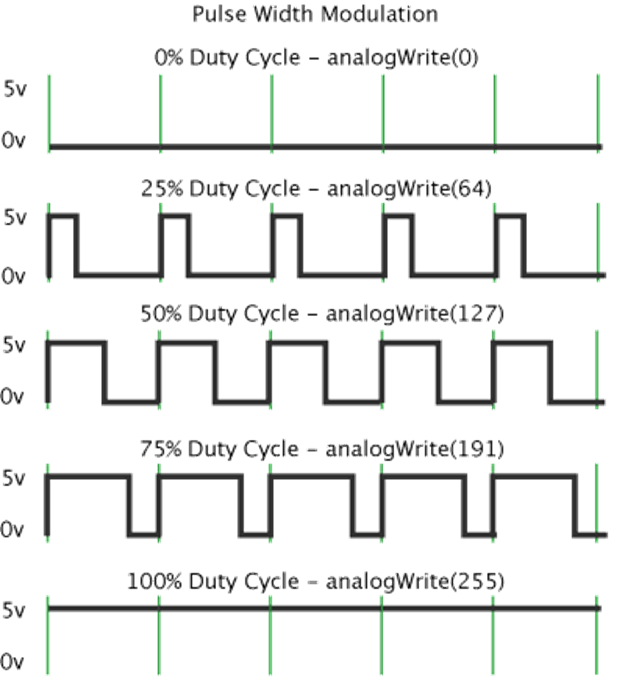
It is a segment of signals, each segment represents multiple points, and then the data is represented by each segment.
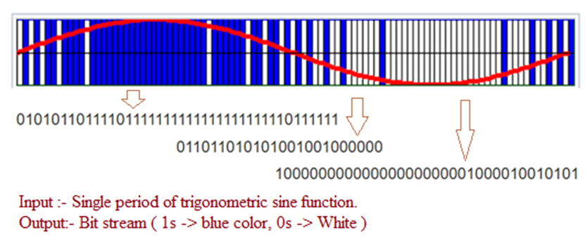
PDM Modulator
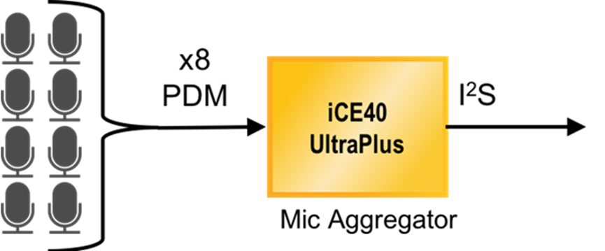
PDM is capable of transferring analog voltages into a single bit data stream. the output of PDM is PCM data that needs to be transferred via the I2S protocol. Compared to PCM has a higher sampling rate, because PCM by segment bytes to sample the audio data representation.
This is increasingly used in microphone acquisition and can be used to acquire high power consumption and high fidelity data.
Here are the example product:
The microphone can’t be directly connected to the I2S device after capture, it needs to be connected to a codec again.
Refereces:
The Difference Comparing
A practical difference is, microcontrollers, even the cheapest ones, offer multiple channels of PWM generators. They rarely offer PDM generators, so even if you’d actually prefer PDM, you end up using PWM because hardware does it for you, often at high clock frequency, so your CPU doesn’t need to run any code in real time, you can just fire-and-forget it.
PDM could be easily implemented in hardware; the pseudocodes Nominal Animal posted for PWM and PDM are both easily translated into digital logic (via hardware description language) and both have small silicon area; but due to tradition you just have PWM.
One may opt for a hybrid solution where the hardware PWM is used with a much shorter period (and hence, lower resolution), then a software loop “dithers” this PWM setpoint. The point is, the software doesn’t need to do this for every output symbol. The result is like a “clumped” PDM; compare these examples (just boring 50% duty because I’m lazier than Nominal Animal):
Code: [Select] https://www.eevblog.com/forum/beginners/pdm-vs-pwm/
Proctol
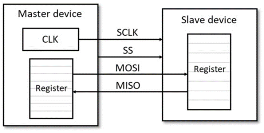
I2C
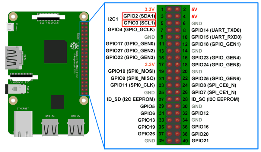
I2C can control multiple devices at the same time, but SPI can only control one. i2c transmits data, i2s transmits audio. i2c is used to transmit audio data, then the transmission of audio band will be very narrow, mainly because it can not do the full frequency range. i2c generally to control registers, but GPIO is the control of the hardware. That is to say, I2C is the SW part, and GPIO is the hardware to control. That is, the software to write registers is I2C control, hardware is GPIO pull pin to control.
I2S
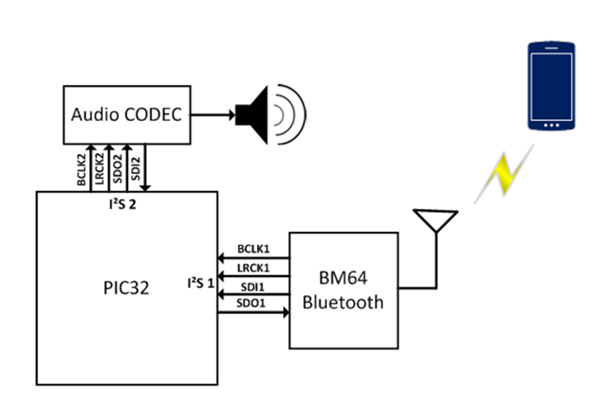
I2S cannot be used in the same way as I2C and is generally only used for audio devices. I2C can have multiple masters, but I2S can only have one. I2S performs better for audio transmission and is used to transmit PCM data, so that the codec can be directly avoided. https://www.feasycom.com/blog-1050.html
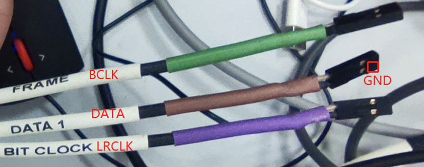
Here the connection should be connected to GND and ground, otherwise it can not be measured.
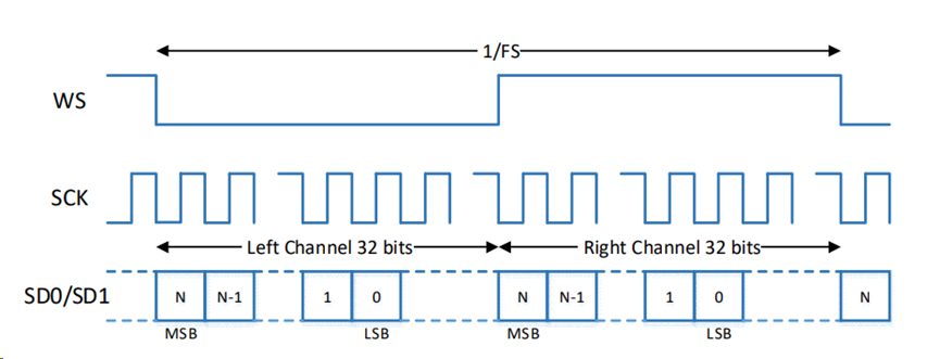
WS/LRCLK
WS is selected for the field (channel), also known as LRCK, which is used to switch the data of the left and right channels. The frequency of LRCK is equal to the sampling frequency; LRCK takes one sample point per clock cycle, BCLK is 64fs, i.e., 64 bits of data per clock cycle.
SCK/BCLK (bit clock)
Serial clock SCK, also called bit clock (BCLK), means that SCLK has 1 pulse for each bit of data corresponding to digital audio. frequency of SCLK = 2 × sampling frequency × number of bits sampled. For supporting 32 bit, BCLK = 244.1HZ32=2.8224MHZ.
SD/TDM DUT_D0: Data pin
Serial Data SD (SDATA), is the audio data expressed in binary complement. In Philips’ I2S standard, both the hardware interface specification and the format of the digital audio data are specified. Sometimes, in order to enable better synchronization between devices, an additional signal MCLK, called the master clock, also called the system clock (Sys Clock), is 256 times or 384 times the sampling frequency.
https://www.cnblogs.com/fellow1988/p/6294362.html
SPI
References:
https://www.crifan.com/common_audio_interface_tdm_pdm_i2s_pcm/
“All this functionality is implemented in a light-weight SPI interface so that any Feather Board can play audio from an SD card.” https://learn.adafruit.com/adafruit-music-maker-featherwing/
Audio Measurements
Microphone measurement methods
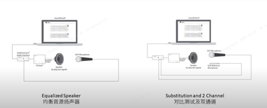
Microphone three measurement methods.
Contrast test method
Compare the reference and the DUT microphone to be tested.
Two-channel transfer
Simultaneous measurement of the reference and the DUT microphone to be tested.
Audio Communication Quality
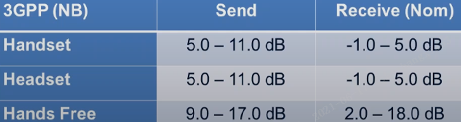
Loudness Level
The loudness of the transmission and reception between the DUT and the network. Provides a known reference loudness value between the network and the DUT.
3GPP standard (narrowband).
Handheld: Transmit: 5.0 ~ 11.0dB Receive: -1.0 ~ 5.0dB
Hands-free: transmit: 9.0 ~ 17.0dB receive: 2.0 ~ 18.0dB
Positive value is attenuation, negative value is gain.
Attenuation is decrease
Gain is to increase.
Loudness level is very strange, positive value means decrease, negative value means increase. But for the hands-free words are to reduce, because it does not need to be to the ear on the line. The inverse square law: If any physical law, the distribution or intensity of a physical quantity decreases in the inverse square of the distance to the source, then this law can be called an inverse square law.
The loudness rating value does not indicate the actual perceived loudness, but rather measures the transmission loss of the system.
The acoustic signal is generally analog and what our human ear can capture, usually SPL sound, but during the channel transmission is voltage, i.e. Volts. It mainly measures the audio signal level between the DUT and the network, and it will affect the compatibility between the DUT and the network. If it is not tuned properly, it will cause the transmitted or received signal to be too loud.
Give a value for the acoustic signal reference, he will give. His presence essentially describes the relationship between y dBPa = x dBV , which allows to get the correct conversion relationship.
The main reason for this is: the DUT is not tuned properly.
Sending direction: is the near-end speakers, sent to the opposite end of the signal is generally reduced by a few dB. because of the reduction of a few dB, so in the receiving side can gain a few dB and then compensate for the loss.
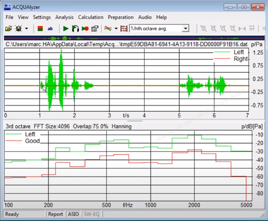
The frequency response is very much related to the loudness level.
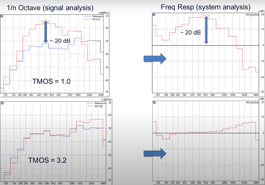
The figure on the right is the difference between the two signals, the difference between the reference curve and the actual received curve, we can see that the difference is very small and very flat, indicating that the device below is a little better.
Reference: ITU-T Recommendation P.79
Frequency Response
Frequency Response: describes how flat the loudness is. Frequency response is very much related to loudness level. The loudness level is an overall level, but the frequency response is a reflection of how smooth the response is. Here we are generally only concerned with how smooth the curve is here, not the size. The red line is the test curve, the blue line is the excitation signal we send to the device, when we subtract the difference between the two signals to get, this is the final of our frequency response curve.
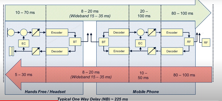
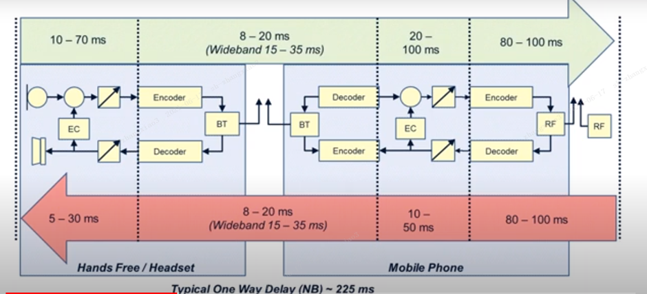
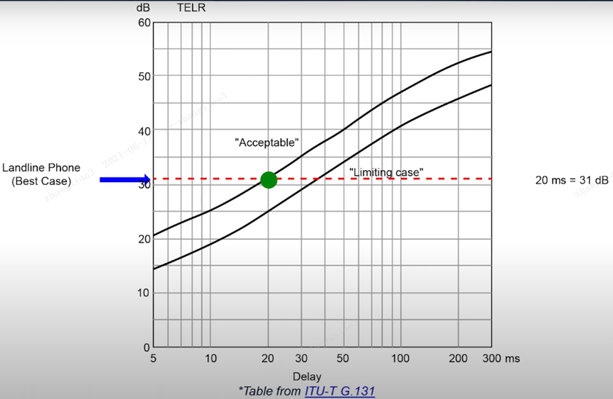
Delay
Can be eliminated by adjusting echo canller. The harder the echo cancellation. Longer delays require more aggressive echo cancellation.
Delay: The delay between the transmission and arrival of the voice signal. The unit is ms. The smaller the better.
Delay does not affect the quality of voice. The smaller the delay, the better.
When I talk to my microphone, the microphone is recorded. The signal recorded by the microphone is sent into the phone via codec.
Delay is generated for a variety of reasons, so its impact factors are many, need to improve the words need to be multiple dimensions to optimize the delay generated as follows. Multiple lines can cause the problem of delay.
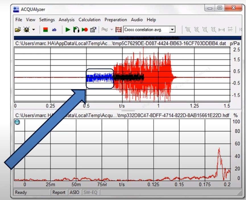
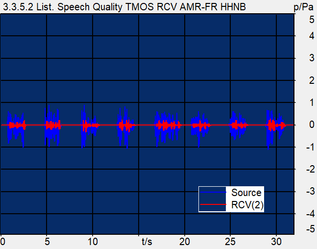
The blue signal at this point is the transmitted excitation signal CSS burst, and the red one is the in-ear reception signal.
Here, the two signals are aligned, they calculate the initial similarity of the signals between each frame, and once the similarity is high, they are aligned, and then the intermediate delay time is calculated as shown by the arrow.
Eg.
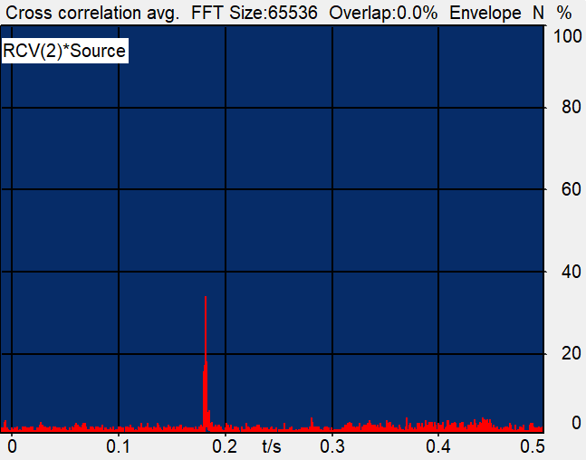
Delay (Cross): 185.23 ms = 0.185 s
Noise:
- Idle Channel Noise.
It is internal noise, similar to the bottom noise. The root cause of the generation of electronic noise in the audio path, low quality speakers or microphones.
It is the noise floor. The internal bottom noise generated by the hardware when there is no signal at all.
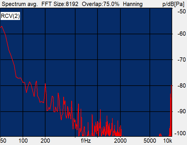
Unit dBm0
Test principle.
Test the response of DUT in a quiet environment
FFT conversion
calculate all the energy values.
The green signal in this is the excitation signal.
SFI (Single Frequency Interference)
Here the red line is the reference, that is, good, green is the actual test data beyond the bad place, the more beyond the more not.In/Out Band Signal
Distortion
Non-linear response of the DUT. Causes: Low quality speakers or microphones, poor dynamic range performance. We tested with a sine signal to excite the response for each frequency band.
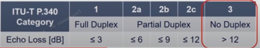
Echo: the bigger the better
Send an excitation signal to the receiving direction, we want to go to test how much echo is sent back from the receiving device, we test in the sending direction. It is when you can hear your voice in the sound sent by the other party, this time it is related to the other party and not to you. Root causes: long latency, devices that are not properly calibrated and no echo cancellation algorithm.
Near-end voice is green, far-end voice is red, and black indicates repeated parts.
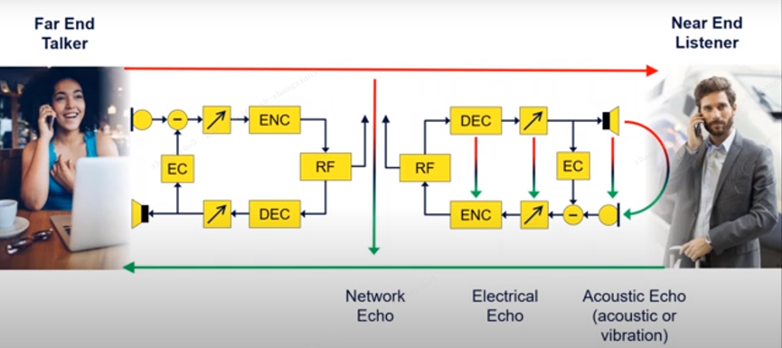
Echo counts is the loss is the echo cancellation effect, the greater the better.
Echo is a problem at the far end.
20ms = 31dB
ITU-T G.131
DOUBLE talk
A method looking for attenuation that occurs during double talk of varying severity.
Double talk has nothing to do with the quality of the call but can affect the experience. It is when one person is talking and other voices suddenly come out and affect the original signal.
Heavy doubletalk: It is when two people say the same text and at the same time. It is the scene of complete overlap.
MOS
We don’t need a professional to listen to it, less time and money spent. The downside is that it doesn’t tell you why the sound quality is poor.
In order to improve the SNR ratio, we usually use linear and nonlinear noise cancellation algorithms. But these algorithms also have some degree of impact on the voice quality, which is difficult to avoid. To test the voice call quality, we measure the quality of voice calls by measuring MOS scores.
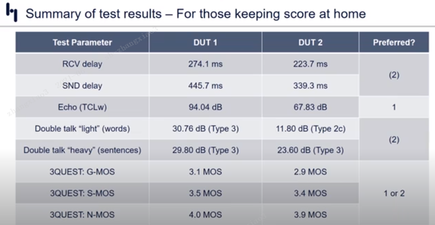
There are three main measures of MOS (Mean Subjective Opinion Score), noise transmission, and overall quality score.
The objective tests in the 3QUEST model test, which includes both wideband and narrowband, mainly include
- Noise MOS score (N-MOS)
The absolute value of background noise, and the effect of background noise on our audio signal.
- Voice MOS score (S-MOS)
Test the SNR value of the voice, naturalness.
- Global MOS score (G-MOS)
Nonlinear merging of S-MOS and N-MOS.
Equipment:
- Head Acoustics GmbH Version 3.5.200
- ACQUA 3 Head System
Summary